The most important reponsibiliteies of data link layer are flow control and error control. Collectively these functions are called data link control
Flow Control
Flow control is a technique used to manage the rate of data transmission between a sender and a receiver so that the receiver is not overwhelmed.
Purpose:
To ensure that a fast sender does not send data faster than a slow receiver can process.
Key Concepts:
- Buffer management: The receiver may have limited buffer space; flow control ensures it doesn’t overflow.
- Transmission rate control: Slows down the sender if the receiver is busy or slow.
Common Techniques:
- Stop-and-Wait Protocol
- Sender sends one frame and waits for an acknowledgment (ACK) before sending the next.
- Sliding Window Protocol
- Sender can send multiple frames before needing an ACK, depending on window size.
- More efficient than stop-and-wait.
Error Control
Error control ensures reliable delivery of data by detecting and correcting errors that occur during transmission.
Purpose:
To ensure that the data received is correct and complete, even if errors occur in the transmission.
Key Functions:
- Error Detection
- Uses techniques like parity check, checksum, or CRC to detect errors.
- Error Correction
- Uses ARQ (Automatic Repeat reQuest) to ask for retransmission if an error is found.
| Feature | Flow Control | Error Control |
|---|---|---|
| Goal | Prevent receiver overflow | Ensure data is accurate and complete |
| Deals with | Speed mismatch | Transmission errors |
| Methods Used | Stop-and-Wait, Sliding Window | ARQ, Checksum, CRC |
| Receiver Role | Controls rate of data received | Detects/corrects errors, sends ACK/NACK |
Noiseless Protocols in Computer Networks
Noiseless protocols are idealized models in the data link layer used to understand reliable communication in the absence of transmission errors. These protocols assume that:
- The communication channel is perfect (no bits are lost or corrupted).
- Frames are received exactly as they are sent.
- Acknowledgments, if used, are never lost.
These protocols help illustrate the concept of flow control without the complexity of dealing with transmission errors.
There are two main types of noiseless protocols:
1. Simplest Protocol
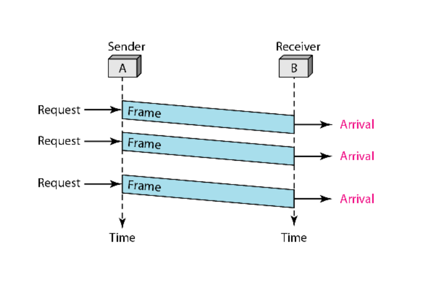
Characteristics:
- Assumes a perfect channel with no possibility of frame loss or corruption.
- Sender sends data continuously without waiting for any acknowledgment.
- Receiver is always ready to accept data.
Working:
- The sender simply sends one frame after another.
- The receiver processes each frame as it arrives.
- There is no synchronization or control mechanism between sender and receiver.
Limitation:
- There is no flow control. If the sender is faster than the receiver, the receiver’s buffer may overflow, leading to data loss (in practical systems).
- It is not practical for real-world use, but it demonstrates basic data transfer.
2. Stop-and-Wait Protocol
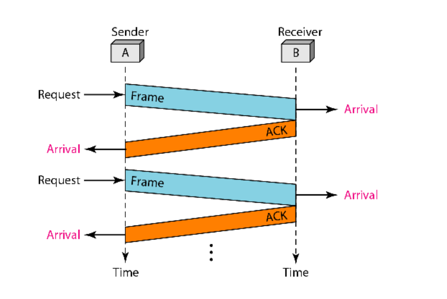
Characteristics:
- Still assumes a noiseless channel (no frame or ACK is lost or corrupted).
- Introduces flow control by ensuring the sender waits for a response from the receiver before sending the next frame.
Working:
- The sender transmits a single frame.
- After sending the frame, the sender waits for an acknowledgment (ACK) from the receiver.
- The receiver receives the frame, processes it, and sends an ACK back.
- Once the sender receives the ACK, it sends the next frame.
Advantages:
- Provides simple flow control.
- Ensures that the receiver is not overwhelmed since only one frame is in transmission at a time.
Limitations:
- Inefficient in high-latency networks because the sender remains idle while waiting for the ACK.
- Only one frame is transmitted at a time, so bandwidth utilization is low.
Noisy Channel?
A noisy channel refers to a communication medium where:
- Bits may flip due to interference, signal degradation, or other noise sources.
- Frames (data packets) may get lost, corrupted, or delivered multiple times.
- Acknowledgments (ACKs) can also be lost or corrupted.
2. How Do Noisy Channel Protocols Work?
To ensure reliable communication over a noisy channel, protocols must handle two main tasks:
- Error Detection: Identify if data was corrupted (using techniques like checksums, CRC, parity bits).
- Error Control: Take action when an error is detected (usually by retransmitting the data).
This is usually done through ARQ (Automatic Repeat reQuest) protocols.
3. Types of Noisy Channel Protocols
a) Stop-and-Wait ARQ
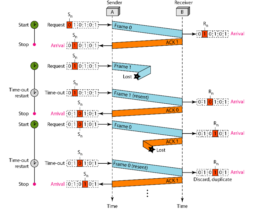
Working:
- The sender sends one frame and waits for an ACK.
- If the ACK is received within a time limit, the sender sends the next frame.
- If the ACK is not received (due to frame or ACK loss), the sender resends the frame after a timeout.
- The receiver discards duplicates using sequence numbers (e.g., 0 and 1).
Characteristics:
- Handles errors by retransmitting lost or corrupted frames.
- Uses a simple sequence number (usually 1 bit) to identify frames.
Limitation:
- Inefficient for long-delay or high-throughput channels because the sender waits a lot.
b) Go-Back-N ARQ
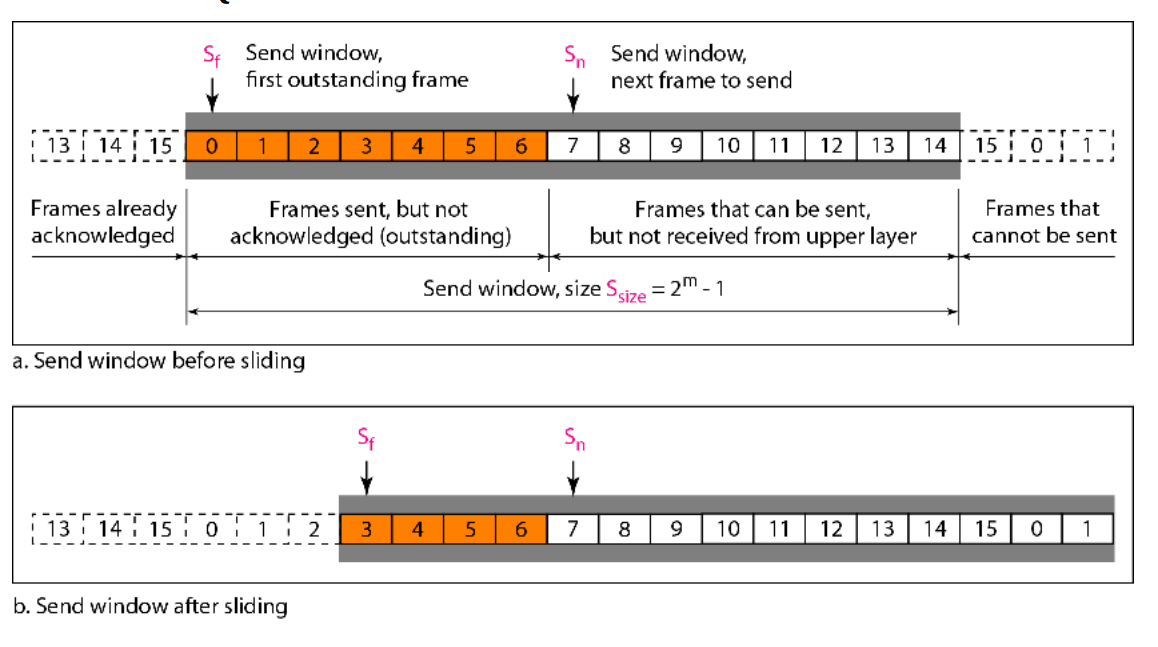
Working:
- The sender can send multiple frames (up to a window size
N) without waiting for individual ACKs. - Receiver sends cumulative ACKs for the last correctly received frame.
- If an error is detected or a frame is lost, the receiver discards all subsequent frames, and the sender must go back and retransmit from the lost frame onward.
Characteristics:
- Improves efficiency by keeping the sender busy.
- Still wastes bandwidth when errors occur because all frames after an error are resent.
c) Selective Repeat ARQ
Working:
- Like Go-Back-N, but the receiver accepts and buffers out-of-order frames.
- Only the specific frame that was lost or corrupted is retransmitted.
- Receiver sends individual ACKs for each frame.
Characteristics:
- More efficient than Go-Back-N in high-error environments.
- More complex due to buffering and tracking multiple ACKs and sequence numbers.
Summary Table
| Protocol | Window Size | ACK Type | On Error | Receiver Behavior | Efficiency |
|---|---|---|---|---|---|
| Stop-and-Wait ARQ | 1 | Per frame | Retransmit one | Processes one at a time | Low |
| Go-Back-N ARQ | N | Cumulative | Retransmit from error onward | Discards out-of-order frames | Medium |
| Selective Repeat ARQ | N | Individual | Retransmit only lost | Buffers out-of-order frames | High |
HDLC?
HDLC (High-level Data Link Control) is a bit-oriented data link layer protocol developed by the International Organization for Standardization (ISO). It is used for reliable communication over both:
- Point-to-point links (between two devices)
- Multipoint links (one sender, multiple receivers)
It supports error control using ARQ (Automatic Repeat reQuest) mechanisms, ensuring data is delivered accurately and in the correct order.
Bit-oriented Protocol
This means HDLC treats the data in the form of a continuous stream of bits, not bytes or characters. Control information (like frame boundaries) is identified using specific bit patterns, not characters. This allows HDLC to be more flexible and efficient, especially for binary data transmission.
ARQ Mechanisms in HDLC
HDLC uses ARQ techniques (like those used in noisy channels) to:
- Detect errors in frames (via CRC).
- Request retransmission of corrupted or lost frames.
- Ensure acknowledgment of correctly received frames.
Topics Discussed in the Section
1. Configuration
This defines the roles of devices in communication:
- Primary Station: Controls the link and sends commands.
- Secondary Station: Responds to commands from the primary.
- Combined Station: Can act as both primary and secondary.
2. Transfer Modes
These define how communication is managed:
- Normal Response Mode (NRM): Secondary can send data only when asked by the primary (used in unbalanced configurations).
- Asynchronous Response Mode (ARM): Secondary can initiate communication without permission.
- Asynchronous Balanced Mode (ABM): Both stations are equal and can initiate communication at any time (used in balanced configurations).
3. Frames
HDLC uses three types of frames:
- Information (I) frames: Carry user data.
- Supervisory (S) frames: Provide control information like ACK, NAK.
- Unnumbered (U) frames: Used for control functions such as link setup or disconnection.
Common HDLC Frame Fields
Each HDLC frame, regardless of type, consists of the following key fields:
- Flag (01111110)
- This is a special bit pattern that marks the beginning and end of a frame.
- It helps in frame synchronization.
- Always has the value
01111110(in binary).
- Address
- Identifies the destination station or device.
- Can be 1 or more bytes, depending on configuration.
- Important in multipoint networks, where multiple receivers exist.
- Control
- This is the heart of the frame. It determines the type of frame (I, S, or U).
- Also used for sequencing, acknowledgments, flow control, and error control.
- FCS (Frame Check Sequence)
- Used for error detection.
- Typically a 16-bit or 32-bit CRC (Cyclic Redundancy Check).
- Ensures data integrity.
I-frame (Information Frame)
Used for: Transmitting user data along with flow and error control information.
Structure:
Flag | Address | Control | User Information | FCS | Flag
Details:
- User Information: Actual data from higher layers.
- Control field:
- Contains send and receive sequence numbers.
- Used for error control (ARQ) and flow control.
- Bit structure includes:
N(S): Send sequence number.N(R): Receive sequence number (acknowledgment).- P/F (Poll/Final) bit for command-response coordination.
S-frame (Supervisory Frame)
Used for: Supervision (control) without data transmission. For example, ACKs, NAKs, and flow control.
Structure:
Flag | Address | Control | FCS | Flag
Details:
- No data payload.
- Control field includes:
- Type of supervisory function:
- RR (Receive Ready): Receiver is ready.
- RNR (Receive Not Ready): Receiver cannot accept more frames.
- REJ (Reject): Negative acknowledgment (request retransmission).
- SREJ (Selective Reject): Request for retransmission of specific frame.
- Also includes N(R): Sequence number being acknowledged.
- Type of supervisory function:
3. U-frame (Unnumbered Frame)
Used for: Link management and control signals. Example: establishing or terminating a connection.
Structure:
Flag | Address | Control | Management Information | FCS | Flag
Details:
- Control field:
- Indicates the type of command or response (like link setup, disconnect, reset).
- Does not use sequence numbers.
- Management Information:
- Used for various management functions (e.g., protocol negotiation).
- Optional, depending on frame type.
Connection and Disconnection
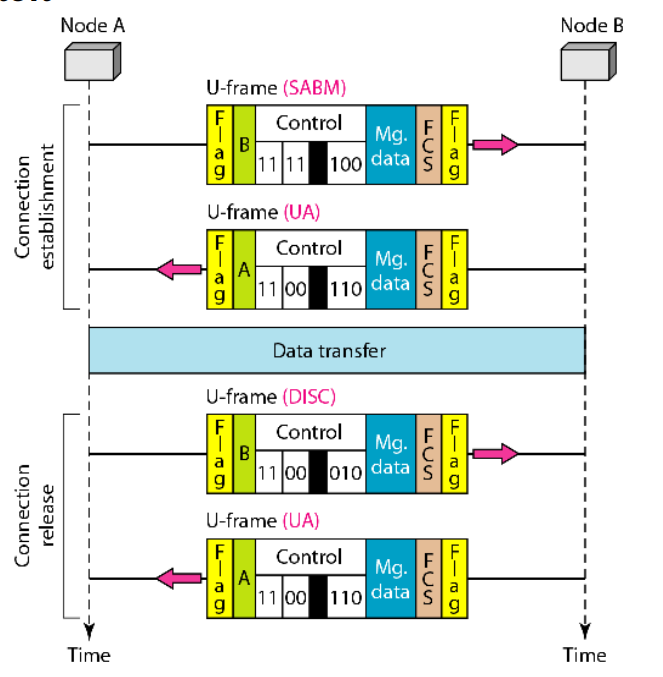
Connection Establishment
U-frame (SABM): Sent from Node A to Node B
- SABM stands for Set Asynchronous Balanced Mode.
- It is used to initiate a connection with balanced (equal) roles between nodes.
- The control field in binary:
11 11 100- First two bits
11= U-frame. - Next bits identify this specific U-frame type (SABM).
- First two bits
- Mg. data (Management Data): May contain parameters for the connection.
- FCS: Ensures data integrity.
- Flag: Marks the beginning and end of the frame.
U-frame (UA): Sent from Node B to Node A
- UA stands for Unnumbered Acknowledgment.
- Sent as a response to SABM to confirm the connection setup.
- Control field:
11 00 110(UA code).
2. Data Transfer
- This phase is not shown in detail but happens after the connection is established.
- I-frames would be used here to carry actual data with sequence numbers, acknowledgments, etc.
3. Connection Release
U-frame (DISC): Sent from Node A to Node B
- DISC stands for Disconnect.
- Requests termination of the data link connection.
- Control field:
11 00 010.
U-frame (UA): Sent from Node B to Node A
- Again, UA is used to acknowledge the disconnect request.
- Same control field:
11 00 110.
Piggybacking
Piggybacking is a technique where the acknowledgment for a received data frame is combined (“piggybacked”) onto an outgoing data frame travelling in the reverse direction. This saves bandwidth by avoiding the need to send separate acknowledgment frames. In the I-frames shown, the Control field typically contains both a send sequence number (for the data being sent) and a receive sequence number (acknowledging data received from the other node).
- Node A sends I-frame (data frame 0) to Node B:
- This is an Information frame (I-frame) carrying data segment 0.
- The Control field shows 0 0. The first 0 is the Send Sequence Number (N(S)) for this frame. The second 0 is the Receive Sequence Number (N(R)), acknowledging that Node A has correctly received frames up to sequence number -1 from Node B (essentially, it’s expecting frame 0 from B next). This second number is the piggybacked acknowledgment.
- Node B receives this frame successfully.
- Node A sends I-frame (data frame 1) to Node B:
- This I-frame carries data segment 1.
- Control field: 1 0. N(S)=1, N(R)=0 (still expecting frame 0 from B).
- Error: This frame is marked as Lost during transmission. Node B never receives it.
- Node A sends I-frame (data frame 2) to Node B:
- Node A, unaware of the loss, continues sending the next frame in sequence.
- This I-frame carries data segment 2.
- Control field: 2 0. N(S)=2, N(R)=0.
- Node B receives this frame.
- Node B’s Reaction to I-frame 2:
- Node B successfully received frame 0. It was expecting frame 1 next.
- However, it receives frame 2 instead. This indicates that frame 1 was missed (lost or corrupted).
- According to the protocol rules (likely a Go-Back-N or Selective Reject variant), Node B Discards frame 2 because it’s out of order.
- Node B sends S-frame (REJ 1) to Node A:
- To signal the error, Node B sends a Supervisory frame (S-frame).
- Type: REJ (Reject), which acts as a Negative Acknowledgment (NAK).
- Control Field: 10 REJ 1. The 1 associated with REJ indicates that Node B is requesting the retransmission of I-frame starting from sequence number 1. It implicitly acknowledges receipt of frames up to 0. (10 likely represents control bits defining the S-frame type).
- Node A’s Reaction to REJ 1:
- Node A receives the REJ 1. It understands that frame 1 (and any subsequent frames it sent, like frame 2) were not correctly received by B.
- Node A prepares to retransmit starting from frame 1.
- Node A resends I-frame (data frame 1) to Node B:
- This is a retransmission of the previously lost frame.
- Control field: 1 0. N(S)=1, N(R)=0.
- Node B receives this frame successfully. Now it has frame 0 and frame 1 in order.
- Node A resends I-frame (data frame 2) to Node B:
- Node A continues the retransmission sequence.
- Control field: 2 0. N(S)=2, N(R)=0.
- Node B receives this frame successfully. Now it has frames 0, 1, and 2 in order.
- Node B sends S-frame (RR 3) to Node A:
- Node B has now successfully received frames 0, 1, and 2 in sequence.
- It sends an S-frame of type RR (Receiver Ready), which acts as a positive Acknowledgment (ACK).
- Control Field: 10 RR 3. The 3 associated with RR indicates that Node B has received all frames up to sequence number 2 correctly and is now ready for (expecting) frame number 3.
Point to Point protocol
This is a specific protocol under HDLC, designed for point-to-point connections. It’s byte-oriented, meaning it handles data in bytes (8-bit units). PPP is widely used to establish direct connections, like between a computer and an ISP (Internet Service Provider) over a serial link.
Topics Covered in the Section
-
Framing:
- Framing in PPP refers to how data is packaged into frames for transmission. A frame is a unit of data that includes the actual data (payload) plus control information like headers and trailers.
- PPP uses a specific frame structure derived from HDLC. The frame typically includes:
- Flag: A special byte (usually 0x7E) to mark the start and end of a frame.
- Address and Control Fields: In PPP, these are often simplified since it’s point-to-point (no need for complex addressing).
- Protocol Field: Identifies the type of data in the payload (e.g., IP, IPv6).
- Payload: The actual data being sent.
- Checksum (FCS): Frame Check Sequence for error detection.
- PPP ensures that the flag byte doesn’t appear in the payload by using a process called byte stuffing (if 0x7E appears in the data, it’s escaped with a special character).
-
Transition Phases:
- PPP connections go through several phases to establish, maintain, and terminate a link. These phases are part of the PPP state machine:
- Dead Phase: No connection exists; the link is down.
- Establish Phase: The two devices negotiate connection parameters using the Link Control Protocol (LCP). They agree on settings like authentication, compression, and maximum frame size.
- Authenticate Phase: Optional authentication (e.g., using PAP or CHAP) to verify the identity of the devices.
- Network Phase: Network-layer protocols (like IP) are configured using protocols like IPCP (IP Control Protocol).
- Open Phase: Data transfer happens here; the link is fully operational.
- Terminate Phase: The connection is closed, and the link returns to the Dead phase.
- Understanding these phases is key for troubleshooting PPP connections.
- PPP connections go through several phases to establish, maintain, and terminate a link. These phases are part of the PPP state machine:
-
Multiplexing:
- Multiplexing in PPP refers to its ability to carry multiple network-layer protocols (e.g., IP, IPX) over the same link.
- The Protocol Field in the PPP frame identifies which protocol the payload belongs to (e.g., 0x0021 for IP, 0xC021 for LCP).
- This allows PPP to support different types of traffic simultaneously, making it versatile for various network setups.
-
Multilink PPP:
- Multilink PPP (MLPPP) is an extension of PPP that allows multiple physical links to be combined into a single logical link.
- For example, if you have two slow connections, MLPPP can bundle them to increase bandwidth and provide redundancy.
- It splits data into fragments, sends them over multiple links, and reassembles them at the other end. This requires sequence numbers to ensure fragments are reassembled in the correct order.
- MLPPP is useful for improving throughput and reliability in scenarios like connecting remote offices.
LCP Packets
LCP is a protocol within the PPP suite that operates at the data link layer. Its primary job is to negotiate and set up the parameters of the PPP link between two devices (like a computer and an ISP). This includes things like agreeing on frame size, authentication methods, and whether to use compression. LCP packets are exchanged during the Establish Phase of a PPP connection (one of the transition phases mentioned in your image) to handle this negotiation.
LCP Packet Structure
LCP packets are encapsulated within PPP frames. Let’s break down the structure step by step:
-
PPP Frame Wrapping:
- Since LCP is part of PPP, an LCP packet is carried inside a PPP frame.
- A typical PPP frame looks like this:
- Flag: 0x7E (marks the start and end of the frame).
- Address: Usually 0xFF (all stations, simplified in PPP).
- Control: Usually 0x03 (unnumbered information, simplified in PPP).
- Protocol: For LCP packets, this field is set to 0xC021 (indicating LCP).
- Information: This is where the LCP packet itself goes.
- FCS: Frame Check Sequence (a checksum for error detection).
- Flag: 0x7E (end of frame).
-
LCP Packet Fields (inside the Information field of the PPP frame):
- Code: 1 byte. Identifies the type of LCP packet (e.g., a request, acknowledgment, or rejection). I’ll list the common types below.
- Identifier: 1 byte. A unique number to match requests with responses. For example, if Device A sends a request with Identifier 0x01, Device B’s response will also use 0x01.
- Length: 2 bytes. The total length of the LCP packet (including Code, Identifier, Length, and Data fields) in bytes.
- Data: Variable length. Contains the specific options being negotiated or messages being exchanged. The format of this field depends on the Code.
So, the LCP packet structure inside the PPP frame’s Information field is:
| Code (1 byte) | Identifier (1 byte) | Length (2 bytes) | Data (variable) |
Types of LCP Packets (Based on the Code Field)
LCP packets are categorized into three main groups based on their purpose: link configuration, link termination, and link maintenance. The Code field determines the packet type. Here are the most common ones:
-
Link Configuration Packets (used to negotiate link parameters):
- Configure-Request (Code 0x01): Sent by a device to propose configuration options (e.g., maximum frame size, authentication protocol). The Data field contains a list of options in Type-Length-Value (TLV) format:
- Type: The option type (e.g., 0x01 for Maximum Receive Unit, MRU).
- Length: Length of the option (including Type and Length fields).
- Value: The value for the option (e.g., MRU = 1500 bytes).
- Configure-Ack (Code 0x02): Sent to accept all options in a Configure-Request. The Identifier matches the request, and the Data field echoes the accepted options.
- Configure-Nak (Code 0x03): Sent to reject some options in a Configure-Request but suggest alternatives. For example, if Device A requests an MRU of 2000 but Device B only supports 1500, the Nak will suggest 1500.
- Configure-Reject (Code 0x04): Sent to reject options that the receiving device doesn’t understand or support. The Data field lists the rejected options.
- Configure-Request (Code 0x01): Sent by a device to propose configuration options (e.g., maximum frame size, authentication protocol). The Data field contains a list of options in Type-Length-Value (TLV) format:
-
Link Termination Packets (used to close the link):
- Terminate-Request (Code 0x05): Sent by a device to request closing the PPP link.
- Terminate-Ack (Code 0x06): Sent to acknowledge the termination request and confirm the link is closing.
-
Link Maintenance Packets (used to monitor the link):
- Code-Reject (Code 0x07): Sent when a device receives an LCP packet with an unknown Code value. The Data field includes the rejected packet.
- Protocol-Reject (Code 0x08): Sent when a device receives a PPP frame with an unsupported protocol (e.g., if the Protocol field isn’t recognized). This isn’t specific to LCP but can be used in the context of LCP.
- Echo-Request (Code 0x09) and Echo-Reply (Code 0x0A): Used to test the link’s status. Echo-Request sends a message, and Echo-Reply confirms the link is alive.
- Discard-Request (Code 0x0B): Sent to test the link by asking the other device to discard the packet (used for debugging).
Common LCP Options (in the Data Field)
During configuration, the Data field of Configure-Request, Configure-Ack, Configure-Nak, and Configure-Reject packets contains options in TLV format. Some key options include:
- Maximum Receive Unit (MRU, Type 0x01): Specifies the maximum frame size the device can receive (default is 1500 bytes).
- Authentication Protocol (Type 0x03): Specifies the authentication method, e.g., PAP (0xC023) or CHAP (0xC223).
- Magic Number (Type 0x05): A random number used to detect looped-back links (if a device receives its own magic number, the link is looped).
- Protocol Compression (Type 0x07): Enables compression of the Protocol field in PPP frames.
- Address/Control Field Compression (Type 0x08): Allows omitting the Address and Control fields in PPP frames to save bandwidth.
How LCP Packets Work in PPP Phases
LCP packets are primarily used during the Establish Phase of a PPP connection:
- Both devices exchange Configure-Request packets to propose their desired options.
- They respond with Configure-Ack (if all options are accepted), Configure-Nak (if some options need adjustment), or Configure-Reject (if some options are unsupported).
- This negotiation continues until both sides agree on the link parameters.
- Once the link is established, LCP can use Echo-Request/Echo-Reply to monitor the link.
- When the connection needs to end (Terminate Phase), Terminate-Request and Terminate-Ack are exchanged.
PAP packets
PAP is a simple authentication protocol used within PPP to verify a device’s identity by sending a username and password in plain text. It’s not secure (since the credentials aren’t encrypted), but it’s still used in some scenarios where security isn’t a major concern or when the underlying link is already secure. PAP operates after the Link Control Protocol (LCP) establishes the link, during the Authenticate Phase of PPP.
PAP Packet Structure
PAP packets are encapsulated within PPP frames, just like LCP packets. Here’s how they fit in:
-
PPP Frame Wrapping:
- PAP packets are carried inside a PPP frame.
- The PPP frame structure is:
- Flag: 0x7E (start/end of frame).
- Address: 0xFF (simplified in PPP).
- Control: 0x03 (simplified in PPP).
- Protocol: For PAP, this is 0xC023 (indicating PAP).
- Information: This contains the PAP packet.
- FCS: Frame Check Sequence (error detection).
- Flag: 0x7E (end of frame).
-
PAP Packet Fields (inside the Information field of the PPP frame):
- Code (1 byte): Identifies the type of PAP packet (e.g., request, success, or failure).
- Identifier (1 byte): A unique number to match requests with responses. For example, a PAP request with Identifier 0x01 will get a response with the same Identifier.
- Length (2 bytes): Total length of the PAP packet (including Code, Identifier, Length, and Data fields) in bytes.
- Data (variable): Contains the authentication details (e.g., username and password) or response messages.
So, the PAP packet structure is:
| Code (1 byte) | Identifier (1 byte) | Length (2 bytes) | Data (variable) |
Types of PAP Packets (Based on the Code Field)
PAP uses three main packet types, identified by the Code field:
-
Authenticate-Request (Code 0x01):
- Sent by the device being authenticated (the “peer”) to the authenticator (e.g., a server).
- The Data field contains:
- Peer-ID Length (1 byte): Length of the username.
- Peer-ID (variable): The username (e.g., “user123”).
- Password Length (1 byte): Length of the password.
- Password (variable): The password (e.g., “pass456”).
- Example Data field: If the username is “user123” and password is “pass456”, the Data field would be:
| 0x07 (Peer-ID Length) | user123 (7 bytes) | 0x07 (Password Length) | pass456 (7 bytes) | - Note: The username and password are sent in plain text, making PAP vulnerable to eavesdropping.
-
Authenticate-Ack (Code 0x02):
- Sent by the authenticator to the peer if authentication succeeds (i.e., the username and password match).
- The Data field contains:
- Message Length (1 byte): Length of the optional message.
- Message (variable): An optional message (e.g., “Welcome!”).
- Example: If the authenticator sends a “Welcome!” message:
| 0x08 (Message Length) | Welcome! (8 bytes) | - The Identifier matches the Authenticate-Request’s Identifier.
-
Authenticate-Nak (Code 0x03):
- Sent by the authenticator if authentication fails (e.g., wrong username or password).
- The Data field contains:
- Message Length (1 byte): Length of the optional message.
- Message (variable): An optional message (e.g., “Invalid credentials”).
- Example: If the authenticator sends “Invalid credentials”:
| 0x12 (Message Length) | Invalid credentials (18 bytes) | - The Identifier matches the Authenticate-Request’s Identifier.
How PAP Authentication Works in PPP
Here’s the step-by-step process of PAP in the PPP Authenticate Phase:
- LCP Negotiation: During the Establish Phase, LCP negotiates the authentication protocol. If PAP is chosen (option Type 0x03, Value 0xC023 in LCP’s Configure-Request), the link moves to the Authenticate Phase.
- Authenticate-Request: The peer sends an Authenticate-Request packet with its username and password.
- Authenticator Response:
- The authenticator checks the credentials against its database.
- If correct, it sends an Authenticate-Ack, and the PPP link moves to the Network Phase (e.g., to configure IP with IPCP).
- If incorrect, it sends an Authenticate-Nak, and the link may terminate or retry (depending on implementation).
- Retries: PAP doesn’t have a built-in retry limit, but implementations often allow a few attempts before terminating the link.
Example Exchange
- Peer sends: Authenticate-Request (Code 0x01, Identifier 0x01, Peer-ID = “user123”, Password = “pass456”).
- Authenticator checks credentials:
- If valid, it responds with Authenticate-Ack (Code 0x02, Identifier 0x01, Message = “Welcome!”).
- If invalid, it responds with Authenticate-Nak (Code 0x03, Identifier 0x01, Message = “Invalid credentials”).
Key Characteristics of PAP
- Plain Text: Username and password are sent unencrypted, making PAP insecure over untrusted networks.
- Two-Way Handshake: Only the peer is authenticated (client-to-server); the authenticator isn’t verified.
- Simple: Easy to implement but not recommended unless the link is already secure (e.g., over a VPN).
Comparison with CHAP (Since It’s an Alternative)
- PAP sends credentials in plain text; CHAP (Challenge Handshake Authentication Protocol) uses a hashed challenge-response mechanism, making it more secure.
- PAP is a two-way handshake; CHAP is a three-way handshake (challenge, response, success/failure).
- During LCP negotiation, the authentication protocol is chosen (PAP = 0xC023, CHAP = 0xC223).
CHAP
CHAP is an authentication protocol within PPP that verifies a device’s identity using a three-way handshake and a shared secret (password). Instead of sending the password directly, CHAP uses a challenge-response mechanism with hashing, making it more secure than PAP. It’s negotiated during the LCP phase (authentication protocol option, Type 0x03, Value 0xC223) and executed in the Authenticate Phase.
CHAP Packet Structure
CHAP packets are encapsulated in PPP frames, similar to PAP and LCP packets. Here’s the breakdown:
-
PPP Frame Wrapping:
- CHAP packets are carried inside a PPP frame.
- The PPP frame structure is:
- Flag: 0x7E (start/end of frame).
- Address: 0xFF (simplified in PPP).
- Control: 0x03 (simplified in PPP).
- Protocol: For CHAP, this is 0xC223 (indicating CHAP).
- Information: Contains the CHAP packet.
- FCS: Frame Check Sequence (error detection).
- Flag: 0x7E (end of frame).
-
CHAP Packet Fields (inside the Information field of the PPP frame):
- Code (1 byte): Identifies the type of CHAP packet (e.g., challenge, response, success, or failure).
- Identifier (1 byte): A unique number to match requests with responses (e.g., a challenge and its response share the same Identifier).
- Length (2 bytes): Total length of the CHAP packet (including Code, Identifier, Length, and Data fields).
- Data (variable): Contains the challenge, response, or result message, depending on the packet type.
So, the CHAP packet structure is:
| Code (1 byte) | Identifier (1 byte) | Length (2 bytes) | Data (variable) |
Types of CHAP Packets (Based on the Code Field)
CHAP uses four main packet types, identified by the Code field:
-
Challenge (Code 0x01):
- Sent by the authenticator (e.g., a server) to the peer (e.g., a client) to start the authentication process.
- The Data field contains:
- Value-Size (1 byte): Length of the challenge value.
- Value (variable): A random challenge string (usually 16 bytes or more, generated by the authenticator).
- Name (variable): The authenticator’s name (used by the peer to look up the shared secret).
- Example: If the challenge value is a 16-byte random string and the authenticator’s name is “Server1”:
| 0x10 (Value-Size) | <16-byte random string> | Server1 (7 bytes) |
-
Response (Code 0x02):
- Sent by the peer back to the authenticator in response to the challenge.
- The Data field contains:
- Value-Size (1 byte): Length of the response value (usually 16 bytes for MD5 hashing).
- Value (variable): The hashed response. The peer calculates this by hashing the Identifier, the shared secret (password), and the challenge value using MD5:
- Hash = MD5(Identifier + Secret + Challenge).
- Name (variable): The peer’s name (used by the authenticator to look up the shared secret).
- Example: If the response value is a 16-byte MD5 hash and the peer’s name is “Client1”:
| 0x10 (Value-Size) | <16-byte MD5 hash> | Client1 (7 bytes) |
-
Success (Code 0x03):
- Sent by the authenticator if the peer’s response matches the expected hash (authentication succeeds).
- The Data field contains:
- Message (variable, optional): A success message (e.g., “Authentication successful”).
- Example: If the message is “Auth OK”:
| Auth OK (7 bytes) |
-
Failure (Code 0x04):
- Sent by the authenticator if the peer’s response doesn’t match the expected hash (authentication fails).
- The Data field contains:
- Message (variable, optional): A failure message (e.g., “Authentication failed”).
- Example: If the message is “Auth Failed”:
| Auth Failed (11 bytes) |
How CHAP Authentication Works in PPP
CHAP uses a three-way handshake during the PPP Authenticate Phase:
- LCP Negotiation: During the Establish Phase, LCP negotiates CHAP as the authentication protocol (Type 0x03, Value 0xC223 in LCP’s Configure-Request).
- Challenge: The authenticator sends a Challenge packet with a random value and its name.
- Response:
- The peer looks up the shared secret (password) based on the authenticator’s name.
- It computes the hash: MD5(Identifier + Secret + Challenge).
- The peer sends a Response packet with the hash and its name.
- Verification:
- The authenticator looks up the shared secret using the peer’s name.
- It computes the expected hash using the same formula: MD5(Identifier + Secret + Challenge).
- If the peer’s hash matches the expected hash, the authenticator sends a Success packet; otherwise, it sends a Failure packet.
- Outcome:
- Success: The PPP link moves to the Network Phase (e.g., to configure IP with IPCP).
- Failure: The link may terminate or retry (depending on implementation).
Example Exchange
- Authenticator sends: Challenge (Code 0x01, Identifier 0x01, Value = <16-byte random string>, Name = “Server1”).
- Peer calculates: Hash = MD5(
0x01 + <shared secret> + <16-byte random string>). - Peer sends: Response (
Code 0x02, Identifier 0x01, Value = <16-byte hash>, Name = "Client1"). - Authenticator verifies the hash:
- If it matches: Success (Code 0x03, Identifier 0x01, Message = “Auth OK”).
- If it doesn’t: Failure (Code 0x04, Identifier 0x01, Message = “Auth Failed”).
Key Characteristics of CHAP
- Secure: Passwords aren’t sent over the link; only hashed values are exchanged.
- Three-Way Handshake: Challenge → Response → Success/Failure.
- Periodic Re-authentication: CHAP can re-challenge the peer during the session to ensure continued security.
- Hashing: Uses MD5 by default (though modern implementations may use stronger algorithms like SHA).
Comparison with PAP
- PAP sends username/password in plain text; CHAP uses a hashed challenge-response.
- PAP is a two-way handshake; CHAP is a three-way handshake.
- CHAP’s Protocol field in the PPP frame is 0xC223; PAP’s is 0xC023.
IPCP
IPCP is a Network Control Protocol (NCP) within PPP, specifically for configuring IP (IPv4) over a PPP link. After LCP sets up the link (Establish Phase) and authentication (e.g., PAP/CHAP) succeeds, IPCP negotiates IP-related parameters like IP addresses, DNS servers, and compression settings during the Network Phase.
IPCP Packet Structure
IPCP packets are encapsulated in PPP frames, similar to LCP, PAP, and CHAP packets:
-
PPP Frame Wrapping:
- Flag: 0x7E (start/end of frame).
- Address: 0xFF (simplified in PPP).
- Control: 0x03 (simplified in PPP).
- Protocol: For IPCP, this is 0x8021 (indicating IPCP).
- Information: Contains the IPCP packet.
- FCS: Frame Check Sequence (error detection).
- Flag: 0x7E (end of frame).
-
IPCP Packet Fields (inside the Information field):
- Code (1 byte): Identifies the packet type (e.g., request, ack).
- Identifier (1 byte): Matches requests with responses.
- Length (2 bytes): Total length of the IPCP packet.
- Data (variable): Contains configuration options in Type-Length-Value (TLV) format.
Structure:
| Code (1 byte) | Identifier (1 byte) | Length (2 bytes) | Data (variable) |
Types of IPCP Packets (Based on the Code Field)
IPCP packets are similar to LCP in terms of negotiation. Common types include:
- Configure-Request (Code 0x01):
- Proposes IP configuration options (e.g., IP address).
- Data field: Options in TLV format (e.g., Type 0x03 for IP Address, Value = 192.168.1.10).
- Configure-Ack (Code 0x02):
- Accepts all options in the Configure-Request.
- Data field: Echoes the accepted options.
- Configure-Nak (Code 0x03):
- Rejects some options but suggests alternatives (e.g., suggests a different IP address).
- Configure-Reject (Code 0x04):
- Rejects unsupported options.
- Terminate-Request (Code 0x05) and Terminate-Ack (Code 0x06):
- Used to close the IP layer of the PPP link.
- Code-Reject (Code 0x07):
- Rejects unknown IPCP packet types.
Common IPCP Options (in the Data Field)
Options are in TLV format:
- IP-Address (Type 0x03): Specifies the device’s IP address (e.g., 192.168.1.10).
- Primary-DNS-Server (Type 0x81): Specifies the primary DNS server address.
- Secondary-DNS-Server (Type 0x83): Specifies the secondary DNS server address.
- IP-Compression-Protocol (Type 0x02): Negotiates compression (e.g., Van Jacobson TCP/IP header compression).
How IPCP Works in PPP
- After LCP and Authentication: Once the PPP link is up (post-LCP) and authenticated (post-PAP/CHAP), the Network Phase begins.
- IPCP Negotiation:
- The peer sends a Configure-Request with desired options (e.g., IP-Address = 0.0.0.0 to request an address).
- The other device responds:
- Configure-Ack: Accepts the options.
- Configure-Nak: Suggests alternatives (e.g., assigns an IP like 192.168.1.10).
- Configure-Reject: Rejects unsupported options.
- Negotiation continues until both sides agree.
- IP Communication: Once IPCP negotiation succeeds, IP data can flow over the PPP link.
Example Exchange
- Peer sends: Configure-Request (Code 0x01, Identifier 0x01, IP-Address = 0.0.0.0, requesting an IP).
- Server responds: Configure-Nak (Code 0x03, Identifier 0x01, IP-Address = 192.168.1.10, suggesting an IP).
- Peer sends: Configure-Request (Code 0x01, Identifier 0x02, IP-Address = 192.168.1.10).
- Server responds: Configure-Ack (Code 0x02, Identifier 0x02, IP-Address = 192.168.1.10).